A friend bought some of these from Amazon. I figured out how to flash custom firmware and thought I’d share. It’s similar to a Sonoff switch, but there are some important differences.


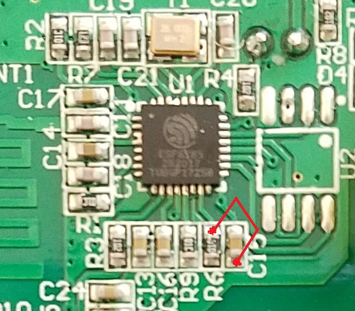
It has a a row of vias/holes for a 4 pin header (top left of middle picture above) like the Sonoff and the ESP-201 boards. You can flash the chip through that header, but compared to the Sonoff and the ESP-201 boards, the TX and RX are reversed on this board! I flashed with the Arduino software, setting the board to ‘generic ESP8285 board’, and I selected ‘1M (64K SPIFFS)’. The switch can be flashed by powering it with 3.3V through the 4 pin connector – disconnect the 120V before doing this. As with all ESP chips, GPIO 0 has to be held low when powering up, to go into flash mode. I did this by using fine tweezers to short the top half of R6 to the bottom half of C15 like this:
So then, the blue WIFI led is controlled by GPIO 13. The LED is on when the IO is LOW.
The relay and the bulb LED are controlled by GPIO 12 – they are on when IO is HIGH.
The capacitive touch switch is connected to GPIO 0 and the IO goes low when touched.
Good luck!
There more discussion about hacking these switches here: https://community.smartthings.com/t/lyasi-wifi-wall-switches-sonoff-plus-ewelink-cloud/

Great job on reverse-engineering this switch. Thanks for posting.
LikeLike
Having you considered submitting a patch to the Tasmota project to add the device to the list of supported modules?
LikeLike
Thank you I was trying to find if it used the esp chipset and was going to try and figure this out, saved me some time. Going to set up some 3 way switch lighting. Flash them use a rule in openhab so when the state changes on two remotes it switches the main
LikeLike
Oh yeah, nice. 3-way switching would be nice. It’s not expensive to include the option in these switches, so I wish they would just do it. Or at least sell a 3-way version that cost an extra 50 cents…. How’d yours work out?
LikeLike
I have seen an ota flash using Tasmota for sonoff wonder if it would work here
LikeLike
If you flash the chip, you can certainly include OTA. I included OTA in the the code I used to flash mine, and now I can update the code with the switch in place. The firmware just needs to include code to allow for OTA. I believe stock sonoff switches include a proprietary OTA option which someone reverse engineered. I’m not aware these switches have any updating option in the stock firmware.
LikeLike
which firmware are you using, I flashed it with the basic sonoff ESP from smartthings website, but the touch button
doesn’t work, only through the app.
LikeLike
Hmm, that’s surprising. I wrote my own code that i’m using, but I’d think the sonoff code would work. The sonoff (basic version, anyway) button is GPIO0, and this capacitve button is connected to GPIO0 as well.
LikeLike
Does someone knows how to turn off the wifi led indicator once its setup and working. I cant sleep with those two bright blue lights in my face.
Thank you!
LikeLike
Did you flash the chip or are using it the way it came? If you didn’t flash custom firmware, I don’t think you disable the lights. You could block the light by taking it apart and removing or covering the leds with tape.
LikeLike
I got a couple of these switches (pretty sure they are the same – I’m not doing what you all are by putting custom f/w on them) and when trying to put in to wifi setup mode, they seem to display a blink code. If I record the blink code, would someone be able to explain what it means? It’s not changing my decision to return them to Amazon, I just really want to know what the blink code means.
LikeLike
Sorry, I don’t know what the flash codes mean. Good luck
LikeLike